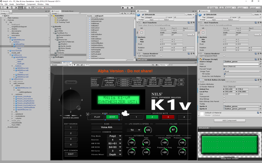
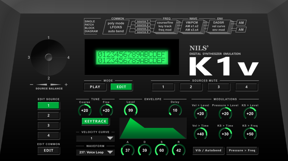
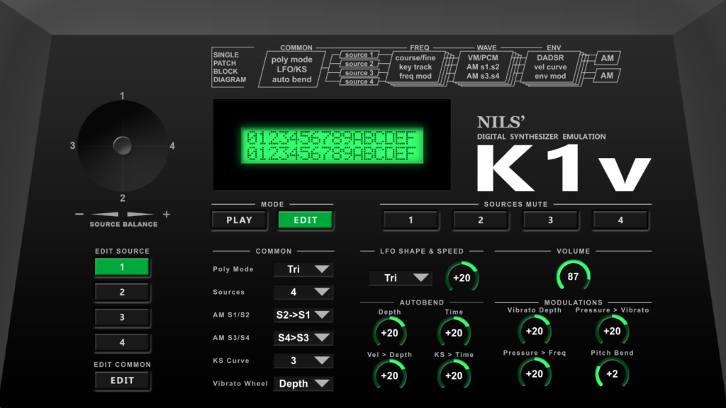
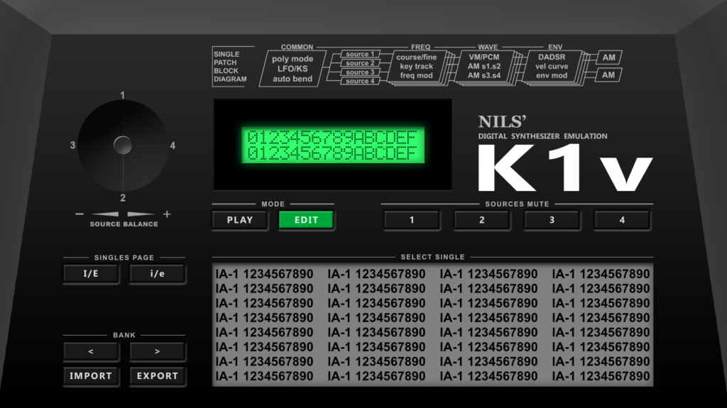
During past weeks, I worked a lot on the User Interface. For faster iteration times, I did the layout in Unity3D and wrote an exporter to create an xml and bitmaps for VSTGUI. This allowed me to do adjustments to the layout very quickly:
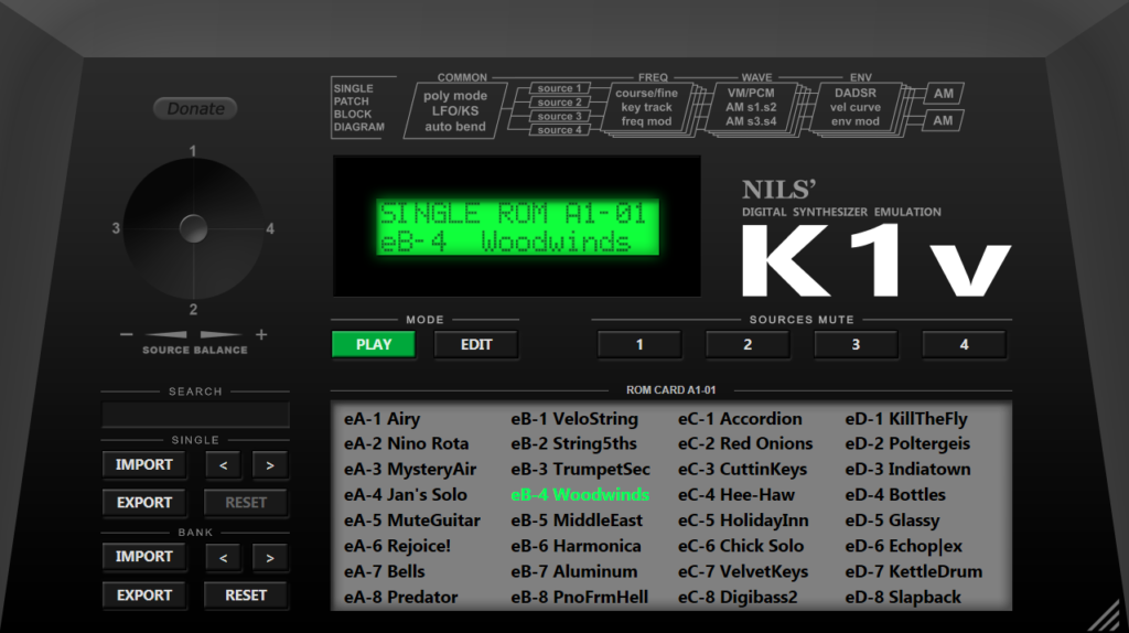
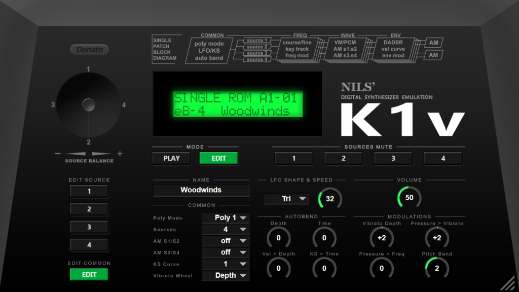
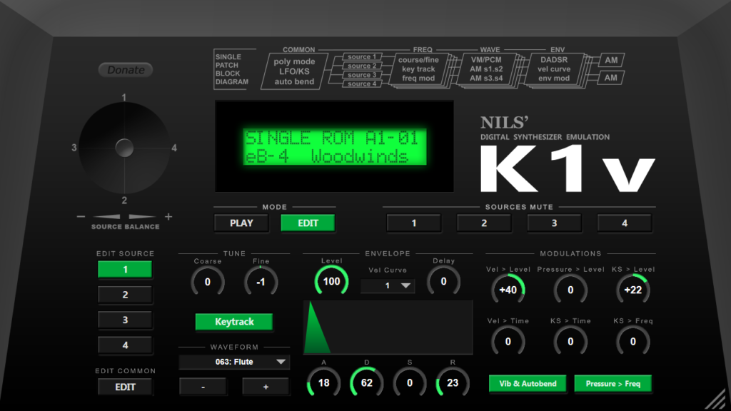
The first layouts that I posted some time ago had to get some updates. I forgot a section to set the name of a Preset and the Play mode page had to get some additional buttons, plus a search box to find presets quickly.
Some people pointed out that it would be better to have all sources on one page for faster editing. I tried it, but it just didn’t fit on one page properly. I didn’t want to ruin the design completely and the editing functionality is already really good in my opinion.
For the emulation engine, I had to do some minor finishing touches and fixed some bugs:
Ring Modulation didn’t behave correctly when being set to reverse mode
Fixed ring modulation caused envelopes to be applied twice, resulting in wrong decay & release behaviour
Implementation of Poly 2, Poly 1 and Mono modes was still missing
K1v will now correctly respond to Sysex messages, just as a real K1 does
Support to mix Source levels with the Joystick
Some code fixes to support 64 bit compilation
Midi: Pan, Main Volume, Program Change including Bank Select, Hold Pedal, All Notes Off
State serialization to make it possible that the state is saved as part of a DAW project
I’ve got many questions about the VST plugin, so I wanted to give some more & updated information about it.
VST Version & Operating System Support
Initial plugin will be a VST 2.4 plugin (VST3 later)
Two versions will be available from start, x86 and x64
As I don’t own a Mac and I’m not familiar with Mac programming, I can’t port it easily to a Mac AU. I have a colleague that could help out here, don’t expect it too soon though.
Features
Instead of the original voice limit of 8/16 voices, the plugin will have unlimited voices
It will contain the K1 factory bank, the K1-II factory bank and all ROM cards, giving a total of 768 Single presets. Multi support is not planned for the first version.
Full editing capability (see UI section below)
SysEx import & export, which will basically make the plugin become a possible editor for a real K1
All Single parameters can be VST automated + the Source Mix Stick will get two automatable parameters
MIDI
The plugin will support all MIDI messages that the real K1 supports such as program changes, Midi CCs, receiving Sysex is supported as well:
All Data Block Dump (i.e. a full Bank of Singles)
Single Data Dump (one Single)
I extended the MIDI feature list compared to a real K1 to now include support for the following additional midi messages:
MIDI CC 10 (Panning, which the K1 did not support)
The K1 Source Mix stick will be mapped to two Midi CCs
Bank Select – Used to switch between the various factory banks and ROM cards. As usual, Bank Select must be send before a Program Change
Pitch Bend wheel will use full precision (K1 is limited to 8 bits)
Most of the Single parameters will be mapped to Midi CCs so they can be edited via an external Midi Controller
UI Mockups
I’ve received a lot of feedback for the very first UI mockup, which wasn’t even finished. I continued working on it to clarify some things. My intention was to have something that someone instantly recognized as being a K1. But of course, at the same time I always wanted the UI to be functional, including full editing capability.
Below are the two editing pages (Common + Source) and the „Play Mode“, where you can browse through the banks / singles.
Hope this clears things up a bit 🙂 And yes, the VST window will be resize-able, maximum resolution is 2560 x 1440
K1v Source Edit ModeK1v Common Edit ModeK1v Play Mode
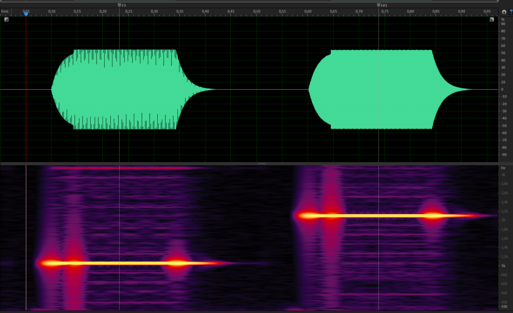
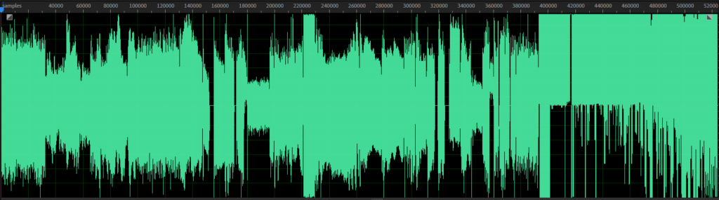
A new audio demo is ready. I kept a lot of the old one but added some additional Singles from the ROM cards and a Vibraphone to demonstrate an AM preset.
Obviously, a big change is that the samples are now from the original K1m Wave ROM. Other than that, all the modulations are now properly implemented and I did a lot of A/B testing to match my real K1m. Without all of this, most of the new sounds (many of them being FX) wouldn’t even work.
Some reverb & EQ has been added, everything else is just the K1 VSTi
Virtual K1 as VSTi – Audio Demo 2
Sound List
0:00 iA-5 Return Home
0:22 Water Drama (K1 ROM card / Kawai PHm)
0:38 iB-3 Jazz Harp
0:46 ID-3 Vybes (Amp Mod demonstration)
0:56 IA-5 Visitors (K1 aliasing demonstration)
1:11 Hold a Key (K1 ROM card / Kawai PHm)
1:19 IA-3 String Pad
1:29 IC-7 Terminator
Bonus
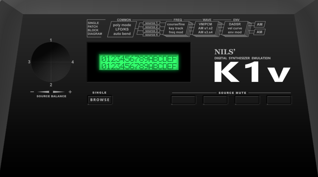
I played around with some UI mockups. Completely work-in-progress of course. The lower section will look different to a real K1m as I want a better editing of course, with envelopes being displayed graphically etc.
After I had finished dumping & integrating the waveforms, I concentrated on the parameter side again. I finished the implementation of all parameters that make up as Single and browsed in the Factory Presets and the ROM cards to do a lot of A/B comparisons to match the original K1. For now, I’m really happy with the sound (new Audio Demo in next post).
Some details about some of the things that I’ve implemented lately:
Updates
Ring Modulation (aka. AmpMod S1S2 / S3S4)
This was pretty much straightforward, what the K1 does is that it multiplies one source with another. The only thing I needed to test here was what happens if a source is muted and what is different when the AmpMod is set to S2>S1 vs REV.
Not really a big deal but as I have been asked if AM would be implemented. Yes, of course.
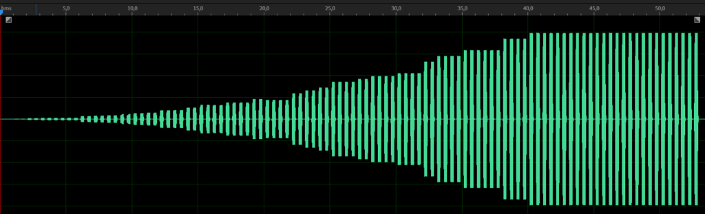
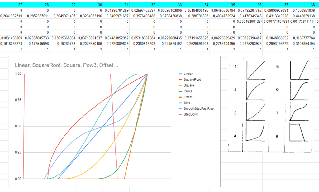
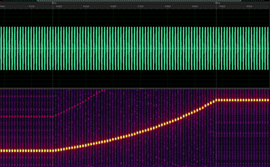
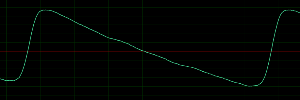
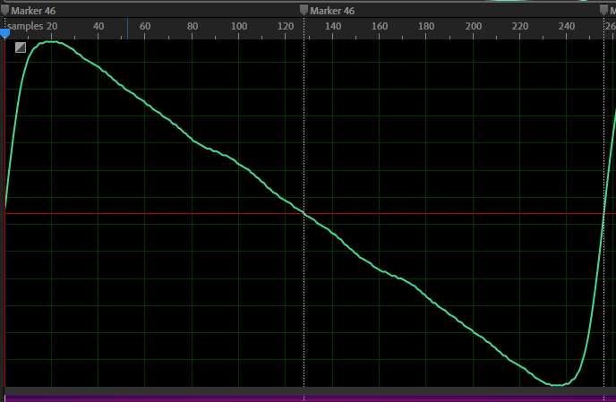
Velocity Curves
I had to do another round of Velocity Curve adjustments. The problem that I was facing is that, if I record all velocity values from 1-127, I get a result that I can easily transfer to an internal table, but the problem is that the recording is affected by the envelope level itself, which is not linear and which I already map.
Velocity Curve 1, velocity from 1 to 127
It would be nice to just use the velocity levels directly for the envelope level, but that doesn’t work because the velocity curves are used to modulate some of other things, too: The envelope attack duration and the autobend depth.
If I would use velocity curves here that are affected by the envelope level already, it gives wrong results. As I didn’t have any change to find out what the velocity values are directly, I used the envelope level values that I recorded and adjusted them in Excel to be a bit closer to the graphs that are printed in the manual. Unfortunately, the graphs in the manual do not match the real results in the recording at all, so I had to do a lot of A/B comparisons to get it right.
Below is an image of my Google Spreadsheet, forgive the bad names for the curves 😎
Kawai K1 Velocity Curves 1-7
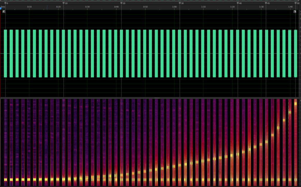
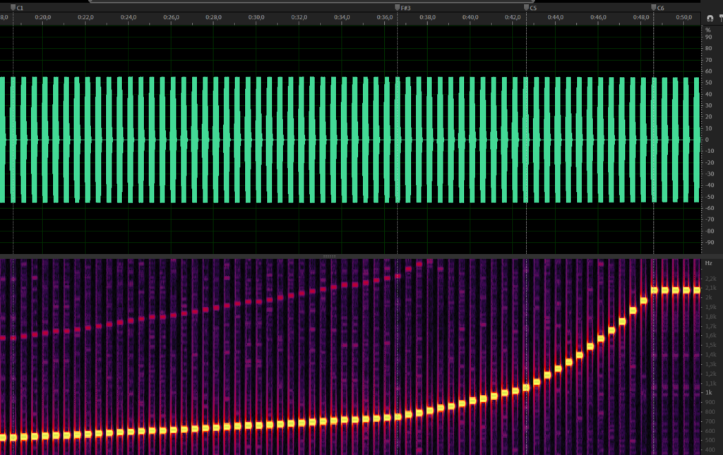
Autobend
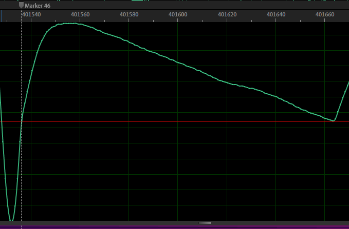
The Autobend implementation in itself was not that complicated, but the autobend depth value had some challenges. If the autobend depth is at maximum or minimum (+50 or -50), the range is exactly one octave up or down. But a value of +/- 25 is not half of an octave, the mapping is completely different. Large values have a much larger effect in the rate of change than lower ones.
I figured out that the mapping is identical to the vibrato depth, which can modulate +/- one octave as well, so I finally had something I have been able to reuse.
I solved the vibrato depth curve some time ago already. I used an LFO set to square and recorded all depth values from 0 to +50 and wrote down the frequency changes as note numbers. I think I didn’t post a picture yet, so here we go:
K1 Vibrato Depth values 0-50
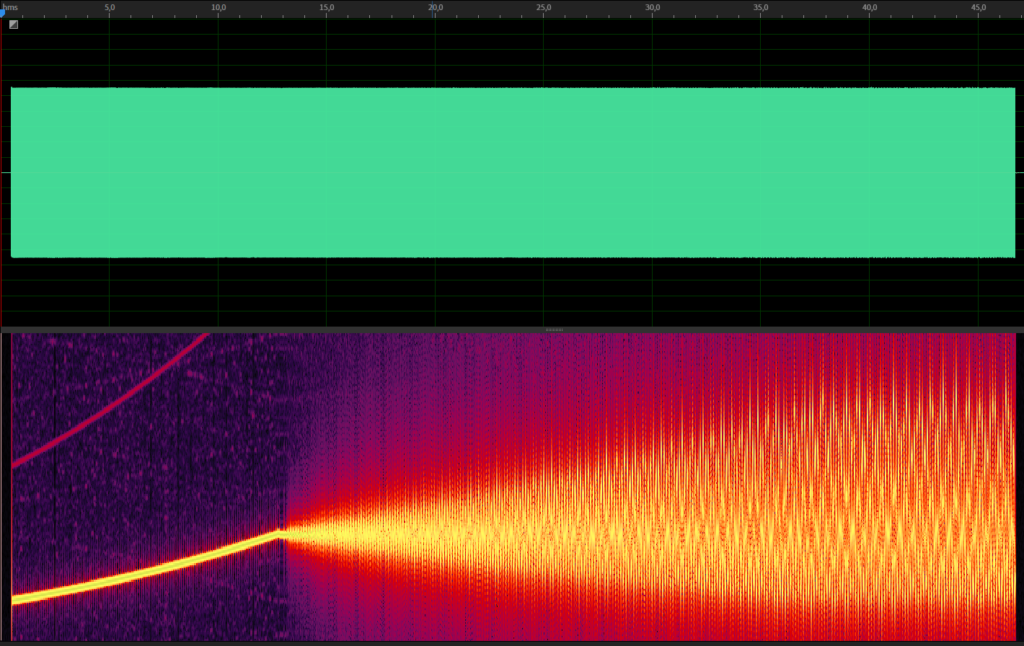
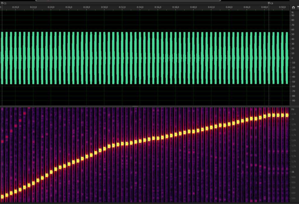
Autobend and vibrato is not very well explained in the manual, the only thing you get out of it is that the vibrato is delayed by the autobend time (whose mapping is identical to the envelope delay time, by the way).
But its not that the vibrato just starts immediately with full strength after the autobend time has elapsed, its fading in. Luckily, the fading is linear so it was easy to implement. After some further testing I came to the conclusion that the fade in duration of the vibrato is twice the autobend time.
Sine curve modulated by autobend + vibrato
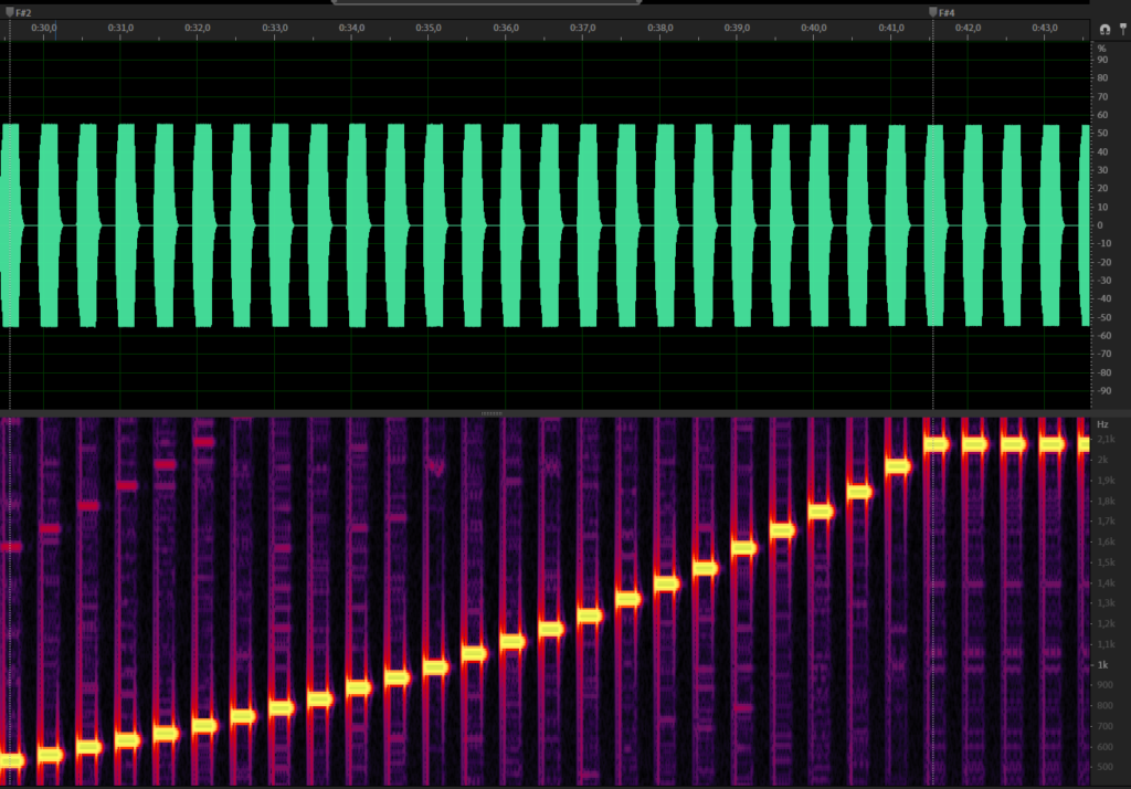
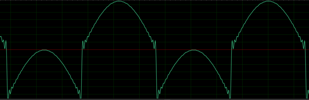
Key Scaling Curves (KS Curve)
The key scaling curves are another thing that I had to record to figure out the mapping. What I found out is that every KS curve is within a range of Midi Notes C1 to C6 (at max, some of them are shorter).
I recorded all of them and did the mapping to note transposes in Excel again. The curves look like this:
Key Scaling Curve 1 Key scaling Curve 2Key Scaling Curve 3Key Scaling Curve 4, basically Curve 1 but narrowed to be in range F#2 to F#4Key Scaling Curve 5, hard transition between F3 and F#3
I was not 100% happy with my waveform recordings, I outlined it briefly in one of my previous articles, where I explained how I recorded them.
The recordings still had the issue of being quite large in size, and more importantly, they contained noise. It’s not just simple noise from some amplifiers (that one is also there, but very low). The K1 resamples the waveforms pretty badly and the aliasing that this produces is clearly audible.
Don’t get me wrong, of course, I want to recreate the aliasing and the dirtyness, as it is part of the K1s character, but it does not help if it is already part of the waveforms, which should be as pure as possible as they are pitched during playback. The aliasing needs to be added at a later stage in the audio generation process. Details about it can be found here.
Furthermore, working with recordings from a device introduces a lot of errors in general: The data has to go through The K1s D/A converters & amplifiers, the cables that go from the K1 to the recording interface and the A/D converters of recording interface itself all introduce small unwanted modifications to the signal
K1 Wave ROM Chip Data
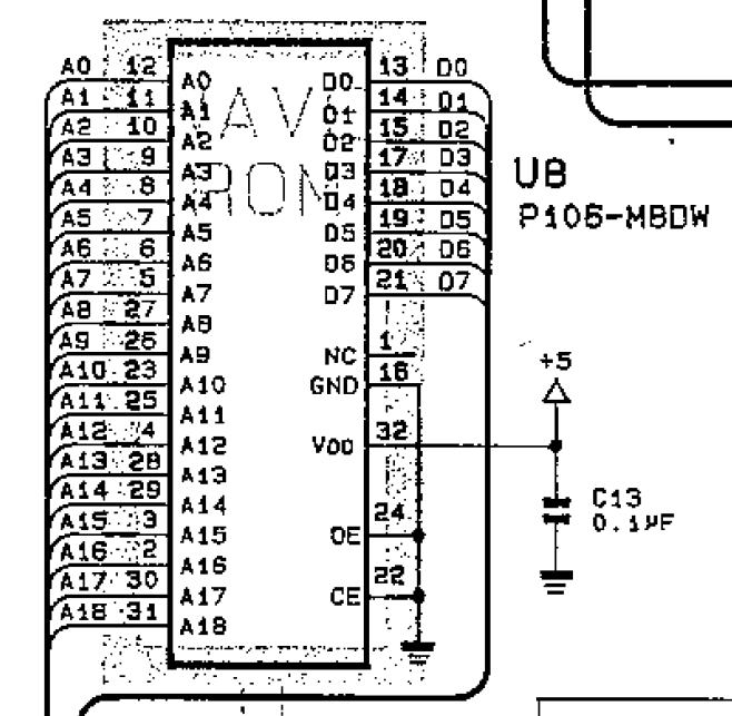
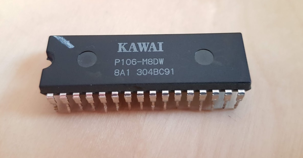
I was browsing the K1 service manual, my intention was to repair my broken K1m, which still suffers from broken envelope attacks, when I noticed the pinout of a chip that had the letters WAVE ROM behind it.
K1 Wave ROM pinout, taken from the service manual
If you have read some of my other articles, you might know that I’m a bit into Home Automation things. For this, I not only buy ready-to-use devices, but also create my own, using Arduinos or similar microcomputers. Given that the pinout of this chip is pretty straightforward, just some address lines and some data lines, I wanted to give it a try.
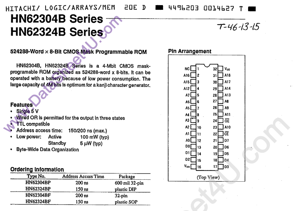
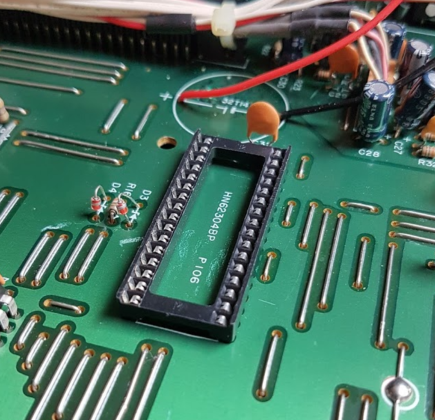
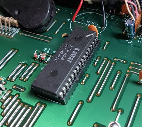
The service manual lists the used chip as being a HN62304BP. I’ve searched the internet and found a data sheet. I verified that the pinout was identical to the Kawai layout.
HN62304BP data sheet
More information that I’ve taken from it: Its size is 4Mbit, or 512KiB and the operating voltage is 5V.
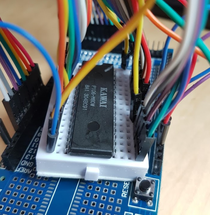
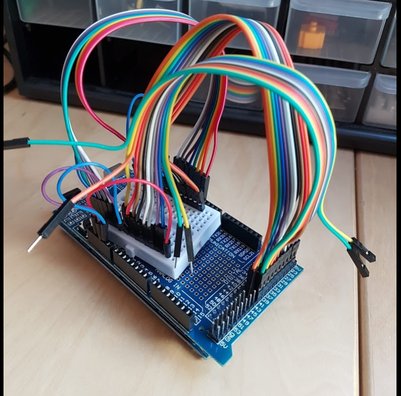
5 Volts perfectly fits an Arduino, but having 19 address lines and 8 data lines, my Arduinos and NodeMCU devices that I have laying around lack plenty of GPIOs for this job. Therefore, I ordered an Arduino Mega 2560 R3 which has a lot of them, 54 digital GPIOs in total.
Preparing the Arduino Mega
I wrote the Arduino code upfront before my order arrived. I used a Google Spreadsheet to help deciding which pins of the Arduino I use to keep the wiring chaos at a minimum. Then, I created some mapping tables in the Arduino Code.
After it arrived, I wired a breadboard to the prototyping shield that came with the Arduino according to the specifications of the ROM chip. After having everything wired up, I was quite happy that it didn’t look too chaotic, definitely maintainable.
A prototyping shield sitting on a Arduino Mega 2560 R3, connected to a breadboard, ready to hold the K1 Wave ROM chip
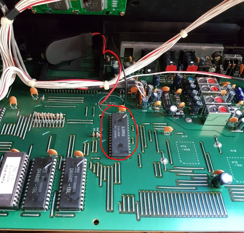
I did a dry run to verify that the code works fine, fixed some issues here and there and then started to desolder the K1m Wave ROM.
Desoldering the Wave ROM
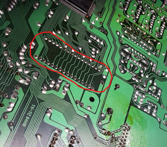
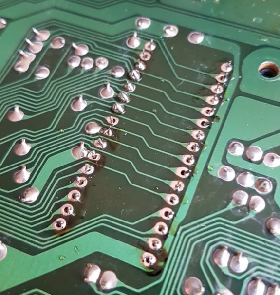
Given that the chip is not socketed , I had some work to do 🤔 I didn’t want to risk ruining the K1 at all costs so I had to be extra careful! The plan was to put the chip back into place after having finished reading it.
I started by adding fresh solder to the pins and furthermore connected each pair of two pins together. This was a preparation for the next step, I heated the new joints up again and used a pump to remove it. The result was pretty good already, some pins required some manual extra work but after a while I was able to remove the chip.
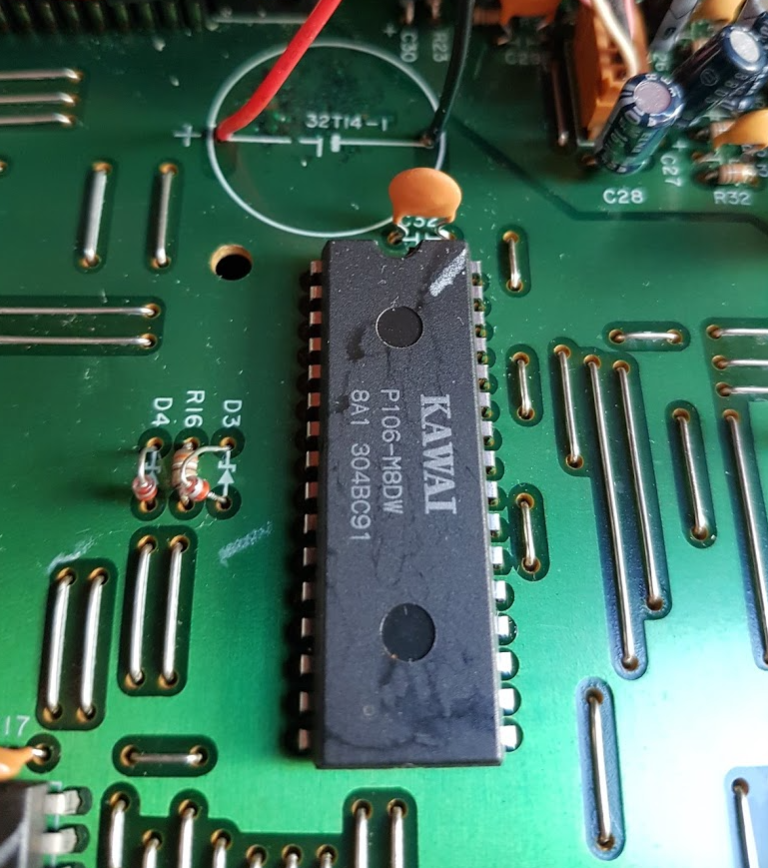
A work-in-progress imageHere we go, the K1m wave rom chipK1m Wave ROM chip on a breadboard
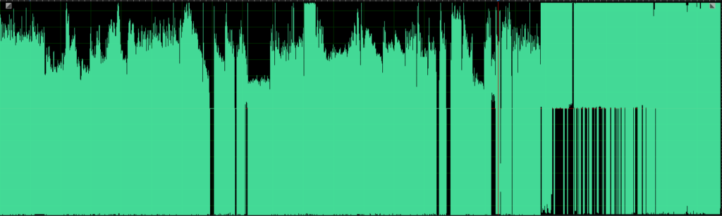
After the dump had finished, I had a first look at it, mainly to verify that my code to dump the ROM was not faulty, I didn’t swap any address lines and such.
I have not been able to find any text or something that would tell me if the dump was correct or not. I verified that all 8 bits are not always zero and not always one, but I couldn’t guess if the data is correct just by looking at it in a hex editor. As it is a Wave ROM, assuming it might contain mostly audio data, I converted the text dump into a binary and loaded it in a wave editor.
When I saw and heared it I was so excited! 😍 Although something was obviously wrong, at the same time, it verified two important of things:
I didn’t swap any address lines or data lines
The ROM had no encryption that I would’ve had to fight against
Wave ROM loaded as PCM data
Though I recognized some of the used waveforms, they appeared to be heavily distorted. I imported them both as signed PCM and unsigned PCM data, but that didn’t help.
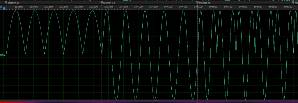
I browsed a bit in the ROM and found the sine single cycle waveform.
Broken Sine wave form
Apparently all negative waveform values were inverted. I added a small code snipped to the wave ROM text-to-binary converter to fix it:
// convert audio data to signed PCM data
for (size_t i = 0; i < data.size(); ++i)
{
	unsigned int d = data[i];
	if (d >= 0x80)
		d = 127 - d;
	data[i] = d & 0xff;
}
After I did that and loaded the wave ROM again I got goosebumps! 👍All waveforms were present, in a quality that is, obviously, much better than anything I had before.
K1m Wave ROM
Wave ROM data analysis
Having the data as audio data, I was able to verify that there is only audio data in it, there is no meta information, such as offsets, any kind of init pattern, whatever. The whole ROM consists of audio data only.
PCM data
I began analyzing the file by adding markers to the waveforms. What I got quite quickly is, that every waveform has a length that is a power of two. The lengths are different, ranging from 4096 samples (some of the drums) to 32768 samples (choir, strings etc).
Knowing that every length is a power of two helped a lot to set the markers at their correct positions, resulting in perfect loop points.
What I also noticed: There are only 30 PCM waveforms in it, although there are 52 PCM waveforms that you can select. This is because the waveforms are used multiple times. For example, there is a one-shot Voice (Wave 233) and a Voice Loop (Wave 238). They are based on the same waveform. This is the same for all loops.
The reversed waveforms that you can select are not present, the K1 generates them in realtime by just playing the waveform backwards.
All „Alt“ loops are not present either. The K1 plays them as forward-backward-forward-… loops.
All „Omnibus“ loops just play through a larger range of the wave ROM. If you listen to the audio above, you can even hear all of them. For example, Omnibus Loop 8 plays a loop consisting of 6 waveforms: F. Guitar, A. Guitar, Piano Noise, Pan Flute Attack, String Attack and Bowed String. Its easy for the K1 because that is the layout in the Wave ROM. The picture below illustrates it.
Omnibus Loop 8 in the Wave ROM
On the left side of the picture, you can see how I named my markers. I use these markers to map segments of the Wave ROM to waveforms 1-256 when I load the Wave ROM in the VSTi plugin.
Single Cycle Waves
The single cycle waves are stored in the Wave ROM, too, but in a much different way.
Single Cycle Waveforms in the Wave ROM
It took me a while to understand what I am looking at. Initially, I thought that my conversion code is broken and that there is still a signed/unsigned/something mismatch.
One of these cycles is always 128 samples long, something that I’ve read previously somewhere. And each cycle seems to exist 5 times. Why? And these snippets are definitely not loopable.
What helped me to understand this is to compare the wave ROM data against my recordings:
Recording of wave 14 (First Saw) Wave ROM data of wave 14 (First Saw)
What the K1 does is, it uses the cycle twice. To form a loop of one waveform, it uses it once in forward mode, the second part is the same cycle, but inverted and negated. If I do this manually in the wave editor, the result looks like this and is a perfect match to the recording:
So what is stored in the ROM are half-cycles only.
The next topic was to figure out why there are always 5 repeats for each waveform. I quickly verified that this is always the case for all single cycle waveforms by calculating the following:
The total data length for all single cycle waveforms in the Wave ROM is 130560 samples
Divided by 5 (number of repeats), the result is 26112
Divided by 128 (length of one cycle), the result is 204. This is the value that we expect as the K1 contains 204 single cycle waveforms
In one of my previous articles, I talked about that some of the single cycle waves are multisamples, and this is what the 5 variations of each waveform are for.
Now the only problem was to find out when to use which multisample. I had another look at my multisample markers that I’ve put into my recordings and noticed that, if there is a multisample transition, they always happen at the same notes. Something that I just didn’t notice. After looking at each of my recordings and writing down the notes, I had a list of 5 different notes that were used, exactly what I was looking for. The final mapping for multisamples is:
Multisample
Midi Note Number Range
1
0-47
2
48 – 59
3
60 – 71
4
72 – 83
5
84 – 127
You may have noticed that the range of one multisample is one octave and that there is support for 5 octaves in total. The reason why I didn’t recognize all multisamples while recording is, that not every waveform uses them. For many waveforms, the data in each multisample is identical.
Conclusion
After adding support to load the Wave ROM in my emulation, the quality increased significantly! 😎 Some of the not-really-good sounding singles now perfectly match the real K1. Especially bell-type sounds that use the amplitude modulation were missing the very low and very high frequencies, now they are as present as on a real K1. I’m going to post new audio demos soon so you can hear the improvements.
One final step is missing: I still have to put the Wave ROM chip back into my K1m. Instead of adding it directly, I’m going to add a socket to the K1m board and insert the Wave ROM there. The socket didn’t arrive yet so I have to wait some days before doing so.
Update: The socket has arrived and the K1 is fine again.
This website uses cookies to improve your experience. We'll assume you're ok with this, but you can opt-out if you wish.AcceptRead More
Privacy & Cookies Policy
Privacy Overview
This website uses cookies to improve your experience while you navigate through the website. Out of these, the cookies that are categorized as necessary are stored on your browser as they are essential for the working of basic functionalities of the website. We also use third-party cookies that help us analyze and understand how you use this website. These cookies will be stored in your browser only with your consent. You also have the option to opt-out of these cookies. But opting out of some of these cookies may affect your browsing experience.
Necessary cookies are absolutely essential for the website to function properly. This category only includes cookies that ensures basic functionalities and security features of the website. These cookies do not store any personal information.
Any cookies that may not be particularly necessary for the website to function and is used specifically to collect user personal data via analytics, ads, other embedded contents are termed as non-necessary cookies. It is mandatory to procure user consent prior to running these cookies on your website.