The K1 is full of aliasing, which is obvious when taking a look at the waveform recordings (see previous article).
Nowadays, it would be pretty straightforward to eliminate the aliasing by doing bandlimited interpolation of the waveforms. But…
What we have to be aware of is that a lot of singles actively make use of aliasing to produce their unique sound. So instead of preventing aliasing, the goal is to recreate the aliasing behavior of the original K1.
What is Aliasing?
To do that, firstly, we have to know what happens when aliasing occurs. Every digital audio device works at a specific sampling rate. For example, a CD player works at a sampling rate of 44100 Hz, or 44,1 KHz. The nyquist theorem states that, given a sampling rate of n, a maximum frequency of n/2 can be represented in an audio stream. In the CD player example, the maximum frequency that can be stored on a CD is 22050 Hz.
If a frequency is generated at runtime, special care needs to be taken to ensure that every frequency is always less than half the sampling rate, aka the nyquist frequency. If the frequency is too high, it starts to mirror at the nyquist frequency, giving unexpected results.
An example: If your audio interface runs at a frequency of 44100 Hz but you try to generate a sine wave of 30000 Hz, it is mirrored at 22050 Hz and begins to fall downwards. Lets do the math:
30000 Hz – 22050 Hz =7950 Hz, so the desired frequency is 7950 Hz too high to be represented correctly.
Mirrored at the nyquist frequency: 22050 Hz – 7950 Hz = 14100 Hz.
So, although we wanted to play a sine wave at 30000 Hz, what we get to hear is a sine wave at 14100 Hz and this is what we call aliasing.
Aliasing on the K1
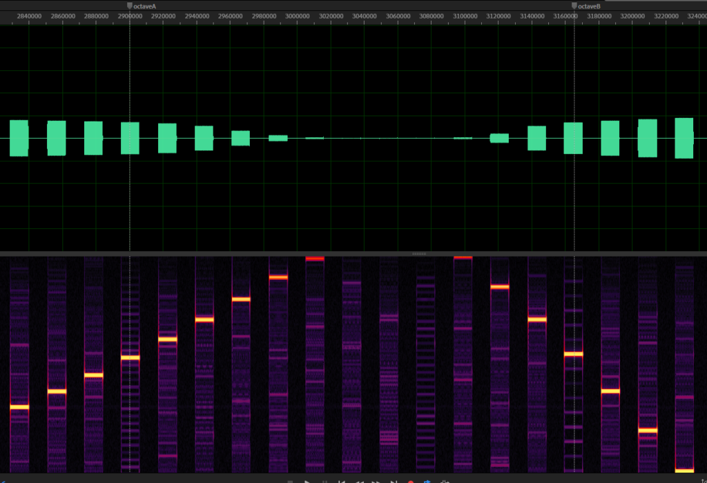
To see aliasing on the K1, take a look at this image:

This is one of the waveform recordings where I played every note from 0 to 127. It starts to alias, but at a frequency that is not known yet.
If you look closer, I added two markers here. The first one is an arbitrary note, the second one is 12 notes away from the first one. I did this because that is exactly one octave higher (note: frequency doubles with each octave) so we can expect that the frequency should be twice as high as the first one, but this is not the case, obviously.
At the first marker, we have a sine wave of roughly 16630 Hz. This should result in the second sine wave being at 33260 Hz. But at the second marker, we observe a sine wave with the frequency of about 16820 Hz instead.
Having both of these values, we can calculate the frequency at which the second sine is mirrored: 33260 Hz – 16820 Hz = 16440 Hz. Half of this value is 8220 Hz and if we add this to the frequency of the first marker the result is 25040 Hz.
The result is our nyquist frequency, which is equal to half sampling rate. If we double this value we get 50080 Hz.
As the FFT frequency analysis is never completely precise and I expect that Kawai has chosen some easy to remember value, I rounded the result which gives us a sampling rate for the K1 of 50000 Hz
Knowing that the sampling rate of the K1 is 50 KHz, I adjusted my emulation to run at the same sampling rate. Furthermore, the waveform playback interpolation has to be kept very basic, for now I have chosen to use very simple linear interpolation. The result is aliasing, identical to the original K1.
A single that makes use of the aliasing is, again, IA-5 Visitors. I added the single to the audio examples, feel free to listen to it here.
Just in case you wonder if that limits the VSTi plugin in any way, don’t worry. It will work on any host sampling rate, I added high quality band limited resampling code that is based on CCRMA/Stanford, as written here: https://ccrma.stanford.edu/~jos/resample/
The K1 emulation engine will always run at 50 KHz and the result will be converted to match the sampling rate of the host.
Great that you want to get the original dirty sound of the K1. Isn’t 48khz a standard frequency?
Indeed, 48Khz is a standard frequency, but the value does not match at all, this results in an error of at least 1Khz
You can easily figure out what kind of interpolation something uses by recording a sound transposed down several octaves. If it’s linear interpolation or trunction, it will be obvious from looking at the waveform, since you will see either line segments or steps. If it’s higher order polynomial interpolation, you can repeatedly differentiate the signal until it resembles steps (use some lowpass filtering to reduce high frequency noise). There are many different varieties of cubic interpolation (for example), but this way you can at least determine the order of the interpolation. If it’s very high order polynomial interpolation or some sort of bandlimited interpolation, this won’t work well, but it works for most things. I think all Kawai hardware uses linear interpolation (except the R100/R50 drum machines, which use truncation).